
| Getting Started |   |
Example: Electrohydraulic Servomechanism
A simple version of an electrohydraulic servomechanism model consists of
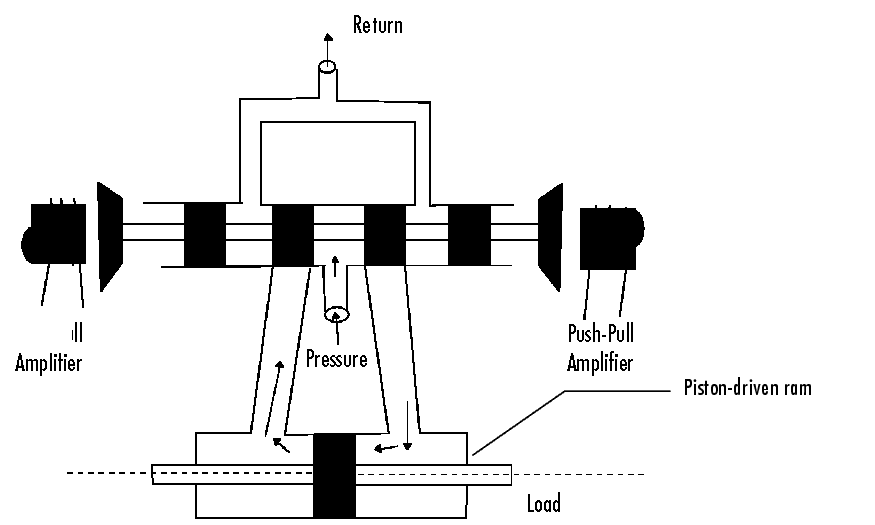
This figure shows a schematic of this servomechanism.

Figure 4-24: An Electrohydraulic Servomechanism
The force on the spool is proportional to the current in the electromagnet coil. As the spool moves, the valve opens, allowing the high-pressure hydraulic fluid to flow through the chamber. The moving fluid forces the piston to move in the opposite direction of the spool. Control System Dynamics, by R. N. Clark, (Cambridge University Press, 1996) derives linearized models for the electromagnetic amplifier, the valve spool dynamics, and the ram dynamics; it also provides a detailed description of this type of servomechanism.
If you want to use this servomechanism for position control, you can use the input voltage to the electromagnet to control the ram position. When measurements of the ram position are available, you can use feedback for the ram position control, as shown in the figure below.

Figure 4-25: Feedback Control Structure for an Electrohydraulic Servomechanism
Your task is to design the compensator, C(s).
Plant Transfer Function
If you have not already done so, type
to load a collection of linear models that include Gservo, which is a linearized plant transfer function for the electrohydraulic position control mechanism. Typing Gservo at the MATLAB prompt displays the servomechanism (plant) transfer function.
Gservo

Zero/pole/gain from input "Voltage" to output "Ram position":
          40000000
-----------------------------
s (s+250) (s^2 + 40s + 9e004)
Design Specifications
For this example, you want to design a controller so that the step response of the closed-loop system meets the following specifications:
The remainder of this section discusses how to use the SISO Design Tool to design a controller to meet these specifications.
Opening the SISO Tool
Open the SISO Design Tool and import the model by typing
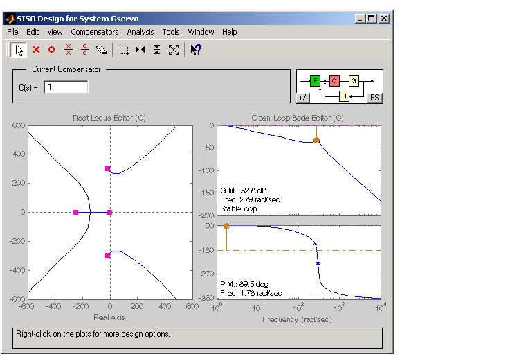
at the MATLAB prompt. This opens the SISO Design Tool with the servomechanism plant imported.

Figure 4-26: SISO Design Tool Showing the Root Locus and Bode Plots for the Electrohydraulic Servomechanism Plant
Zooming
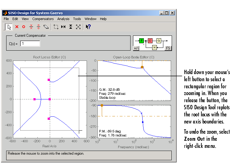
Using the right-click menu in the root locus, select X-Y under Zoom. Hold down the mouse's left button and drag the mouse to select a region for zooming. For this example, reduce the root locus region to about -500 to 500 in both the x- and y-axes. This figure illustrates the zooming in process.

Figure 4-27: Zooming in on a Region in the Root Locus Plot
Alternatively, you use the zoom icons on the toolbar:
 -- Zoom in X
 -- Zoom in Y
 -- Zoom out
As in the DC motor example, open an LTI Viewer by selecting Other Response under Analysis in the menu bar. Click OK on the Response Plot Setup window; the default setting is a closed-loop step response from reference signal r to output signal y. For more information about the Response Plot Setup window, see Customizing Loop Responses in the online documentation under the "Tool and Viewer Reference."
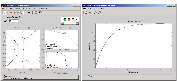
You now should have two windows, the SISO Design Tool and the associated LTI Viewer side by side.

Figure 4-28: SISO Design Tool and Associated LTI Viewer for the Electrohydraulic Servomechanism
The step response plot shows that the rise time is on the order of 2 seconds, which is much too slow given the system requirements. The following sections describe how to use frequency design techniques in the SISO Design Tool to design a compensator that meets the requirements specified in Design Specifications.
 | Root Locus Design | Changing the Compensator Gain |  |