

| Getting Started | |
Changing the Compensator Gain
The simplest thing to do is change the compensator gain, which by default is unity. You can change the gain by grabbing the red squares on the root locus plot and moving them along the curve. This figure shows the procedure.
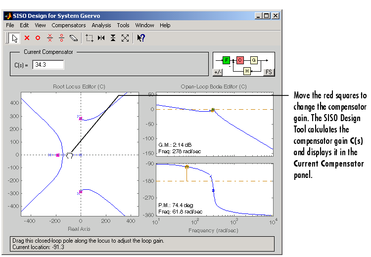
Figure 4-29: Changing the Compensator Gain in the Root Locus Plot
Experiment with different gains and view the closed-loop response in the associated LTI Viewer.
Alternatively, you can change the compensator gain by entering values into the C(s) field in the Current Compensator panel.
Closed-Loop Response
Change the gain to 20 by editing the text box next to Gain, and pressing the Enter key. Notice that the locations of the closed-loop poles on the root locus are recalculated for the new gain set point.
This figure shows the associated closed-loop step response for the gain of 20.
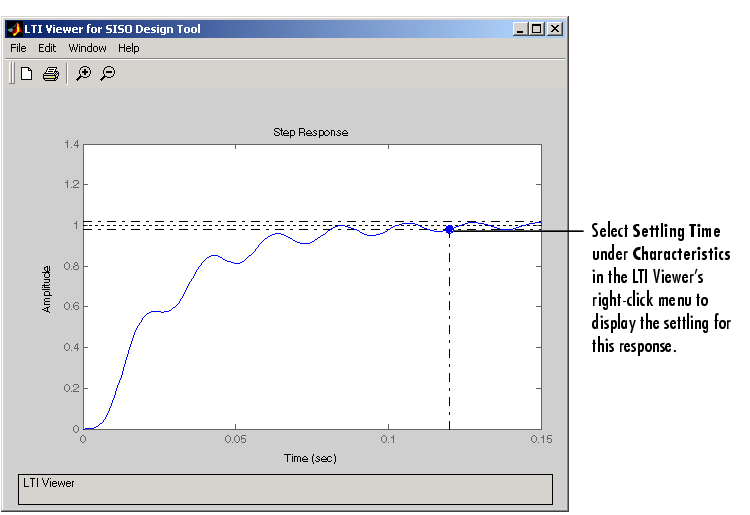
Figure 4-30: Step Response with the Settling Time for C(s) = 20
This closed-loop response does not meet the desired settling time requirement (0.05 seconds or less) and exhibits unwanted ringing. The next section shows how to design a compensator so that you meet the required specifications.
| | Example: Electrohydraulic Servomechanism | Adding Poles and Zeros to the Compensator | |