
| Using Simulink |   |
The control flow blocks are used to implement the logic of the following C-like control flow statements in Simulink:
Although all the preceding control flow statements are implementable in Stateflow, these blocks are intended to provide Simulink users with tools that meet their needs for simpler logical requirements.
Creating Conditional Control Flow Statements
You create C-like conditional control flow statements using ordinary subsystems and the following blocks from the Subsystems library.
| C Statement |
Blocks Used |
if-else |
If, Action Port |
switch |
Switch Case, Action Port |
If-Else Control Flow Statements. The following diagram depicts a generalized if-else control flow statement implementation in Simulink.
Construct a Simulink if-else control flow statement as follows:
u1, u2,..., un and are used to construct output conditions.
u1, u2, ..., un to express conditions for the if, elseif, and else condition fields in the dialog. Of these, only the if field is required. You can enter multiple elseif conditions and select a check box to enable the else condition.
For more detailed information, see the reference topics for the If and Action Port blocks.
| Note All blocks in an Action subsystem driven by an If or Switch Case block must run at the same rate as the driving block. |
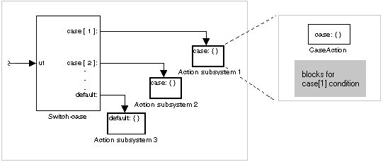
Switch Control Flow Statements. The following diagram depicts a generalized switch control flow statement implementation in Simulink.

Construct a Simulink switch control flow statement as follows:
switch control flow statement. This value determines the appropriate case to execute. Noninteger inputs to this port are truncated.
For more detailed information, see the reference topics for the Switch Case and Action Port blocks.
Creating Iterator Control Flow Statements
You create C-like iterator control flow statements using subsystems and the following blocks from the Subsystems library.
| C Statement |
Blocks Used |
do-while |
While Iterator |
for |
For Iterator |
while |
While Iterator |
While Control Flow Statements
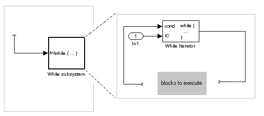
The following diagram depicts a generalized C-like while control flow statement implementation in Simulink.

In a Simulink while control flow statement, the While Iterator block iterates the contents of a While subsystem, an atomic subsystem. For each iteration of the While Iterator block, the block programming of the While subsystem executes one complete path through its blocks.
Construct a Simulink while control flow statement as follows:
while control flow statement as indicated by its new label, while {...}. These subsystems behave like triggered subsystems. This subsystem is host to the block programming you want to iterate with the While Iterator block.
IC) for its first iteration. This must originate outside the While subsystem. If this value is nonzero, the first iteration takes place.
cond. Input for this port must originate inside the While subsystem.
do {...} while. With a do-while iteration, the While Iteration block no longer has an initial condition (IC) port, because all blocks in the subsystem are executed once before the condition port (labeled cond) is checked.
For specific details, see the reference topic for the While Iterator block.
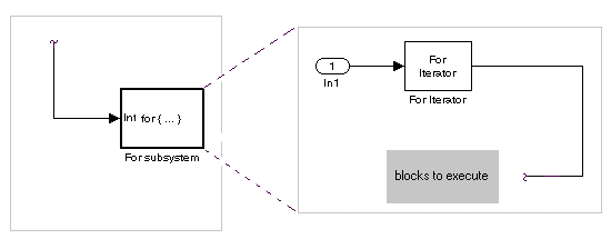
For Control Flow Statements. The following diagram depicts a generalized for control flow statement implementation in Simulink.

In a Simulink for control flow statement, the For Iterator block iterates the contents of a For Iterator Subsystem, an atomic subsystem. For each iteration of the For Iterator block, the block programming of the For Iterator Subsystem executes one complete path through its blocks.
Construct a Simulink for control flow statement as follows:
N. This input must come from outside the For Iterator Subsystem.
You can also set the number of iterations directly in the properties dialog.
The For Iterator block works well with the Assignment block to reassign values in a vector or matrix. This is demonstrated in the following example. Note the matrix dimensions in the data being passed.
The above example outputs the sin value of an input 2-by-5 matrix (2 rows, 5 columns) using a For subsystem containing an Assignment block. The process is as follows:
Comparing Stateflow and Control Flow Statements
Stateflow already possesses the logical capabilities of the Simulink control flow statements. It can call Function-Call subsystems (see Function-Call Subsystems) on condition or iteratively. However, since Stateflow provides a great deal more in logical sophistication, if your requirements are simpler, you might find the capabilities of the Simulink control flow blocks sufficient for your needs. In addition, the control flow statements offer a few advantages, which are listed in the following topics.
Sample Times. The Function-Call subsystems that Stateflow can call are triggered subsystems. Triggered subsystems inherit their sample times from the calling block. However, the Action subsystems used in if-else and switch control flow statements and the While and For subsystems that make up while and for control flow statements are enabled subsystems. Enabled subsystems can have their own sample times independent of the calling block. This also allows you to use more categories of blocks in your iterated subsystem than in a Function-Call subsystem.
Resetting of States When Reenabled. Simulink control flow statement blocks allow you to retain or reset (to their initial values) the values of states for Action, For, and While subsystems when they are reenabled. For detailed information, see the references for the While Iterator and For Iterator blocks regarding the parameter States when starting and the reference for the Action Port block regarding the parameter States when execution is resumed.
Using Stateflow with the Control Flow Blocks
You might want to consider the possibility of using Stateflow and the Simulink control flow blocks together. The following sections contain some examples that give you a few suggestions on how to combine the two.
Using Stateflow with If-Else or Switch Subsystems. In the following model, Stateflow places one of a variety of values in a Stateflow data object. Upon chart termination, a Simulink if control flow statement uses that data to make a conditional decision.
In this case, control is given to a Switch Case block, which uses the value to choose one of several case subsystems to execute.
Using Stateflow with While Subsystems. In the following diagram, Stateflow computes the value of a data object that is available to a condition input of a While Iterator block in do-while mode.
The While Iterator block has iterative control over its host subsystem, which includes the Stateflow Chart block. In do-while mode, the While block is guaranteed to operate for its first iteration value ( = 1 ). During that time, the Stateflow chart is awakened and sets a data value used by the While Iterator block, which is evaluated as a condition for the next while iteration.
In the following diagram, the While block is now set in while mode. In this mode, the While Iterator block must have input to its initial condition port in order to execute its first iteration value. This value must come from outside the While subsystem.
If the initial condition is true, the While Iterator block wakes up the Stateflow chart and executes it to termination. During that time the Stateflow chart sets data, which the While Iterator condition port uses as a condition for the next iteration.
 | Triggered and Enabled Subsystems | Model Discretizer |  |