
| Simulink Reference |   |
Implement a C-like switch control flow statement
Library
Description
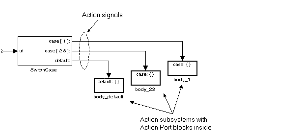
The following shows a completed Simulink C-like switch control flow statement in the subsystem of the Switch Case block.
A Switch Case block receives a single input, which it uses to form case conditions that determine which the subsystem to execute. Each output port case condition is attached to a Switch Case Action subsystem. The cases are evaluated top down starting with the top case. If a case value (in brackets) corresponds to the actual value of the input, its Switch Case Action subsystem is executed.
The preceding switch control flow statement can be represented by the following pseudocode:
switch (u1) {case [u1=1]:body_1;break;case [u1=2 or u1=3]:body_23;break;default:bodydefault;}
You construct a Simulink switch control flow statement like the example shown as follows:
u1 to the source of the data you are evaluating.
Each case can be an integer or set of integers specified with MATLAB cell notation. See the Case conditions field in the "Parameters and Dialog Box" section of this reference.
Action.
case{}.
During simulation of a switch control flow statement, the Action signals from the Switch Case block to each Switch Case Action subsystem turn from solid to dashed.
Data Type Support
Input to the port labeled u1 of a Switch Case block can be a scalar value of any data type, including fixed-point data types, except boolean, int64, and uint64. Noninteger inputs are truncated.
Data outputs are action signals to Switch Case Action subsystems that are created with Action Port blocks and subsystems.
Parameters and Dialog Box
{1,[7,9,4]} specifies that output port case[1] is run when the input value is 1, and output port case[7 9 4] is run when the input value is 7, 9, or 4.{[1:5]} specifies that output port case[1 2 3 4 5] is run when the input value is 1, 2, 3, 4, or 5.Characteristics
| Direct Feedthrough |
Yes |
| Sample Time |
Inherited from driving block |
| Scalar Expansion |
No |
| Dimensionalized |
No |
| Zero Crossing |
Yes, if zero-crossing detection is enabled. |
 | Switch | Switch Case Action Subsystem |  |