
| Simulink Reference |   |
Provide a region of zero output
Library
Description
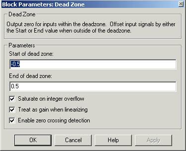
The Dead Zone block generates zero output within a specified region, called its dead zone. The lower and upper limits of the dead zone are specified as the Start of dead zone and End of dead zone parameters. The block output depends on the input and dead zone:
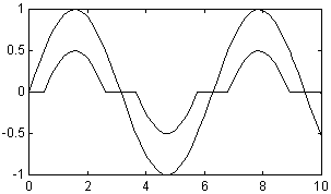
This sample model uses lower and upper limits of -0.5 and +0.5, with a sine wave as input.
This plot shows the effect of the Dead Zone block on the sine wave. While the input (the sine wave) is between -0.5 and 0.5, the output is zero.
Data Type Support
A Dead Zone block accepts and outputs a real signal of any data type except int64 and uint64.
Parameters and Dialog Box
-0.5.0.5.Characteristics
| Direct Feedthrough |
Yes |
| Sample Time |
Inherited from driving block |
| Scalar Expansion |
Of parameters |
| Dimensionalized |
Yes |
 | Data Type Conversion | Demux |  |