
| Simulink Reference |   |
Extract and output the elements of a bus or vector signal
Library
Description
The Demux block extracts the components of an input signal and outputs the components as separate signals. The block accepts either vector (1-D array) signals or bus signals (see Signal Buses in Using Simulink for more information). The Number of outputs parameter allows you to specify the number and, optionally, the dimensionality of each output port. If you do not specify the dimensionality of the outputs, the block determines the dimensionality of the outputs for you.
The Demux block operates in either vector or bus selection mode, depending on whether you selected the Bus selection mode parameter. The two modes differ in the types of signals they accept. Vector mode accepts only a vector-like signal, that is, either a scalar (one-element array), vector (1-D array), or a column or row vector (one row or one column 2-D array). Bus selection mode accepts only the output of a Mux block or another Demux block.
The Demux block's Number of outputs parameter determines the number and dimensionality of the block's outputs, depending on the mode in which the block operates.
Specifying the Number of Outputs in Vector Mode
In vector mode, the value of the parameter can be a scalar specifying the number of outputs or a vector whose elements specify the widths of the block's output ports. The block determines the size of its outputs from the size of the input signal and the value of the Number of outputs parameter.
The following table summarizes how the block determines the outputs for an input vector of width n.
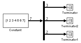
Note that you can specify the number of outputs as fewer than the number of input elements, in which case the block distributes the elements as evenly as possible over the outputs as illustrated in the following example.
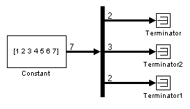
You can use -1 in a vector expression to indicate that the block should dynamically size the corresponding port. For example, the expression [-1, 3 -1] causes the block to output three signals in which the second signal always has three elements while the sizes of the first and third signals depend on the size of the input signal.
If a vector expression comprises positive values and -1 values, the block assigns as many elements as needed to the ports with positive values and distributes the remain elements as evenly as possible over the ports with -1 values. For example, suppose that the block input is seven elements wide and you specify the output as [-1, 3 -1]. In this case, the block outputs two elements on the first port, three elements on the second, and two elements on the third.
Specifying the Number of Outputs in Bus Selection Mode
In bus selection mode, the value of the Number of outputs parameter can be a
2.
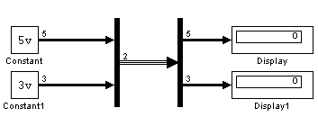
[3, 2], in which case the block outputs three of the input signals on one port and the other two signals on a second port.
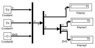
The cell array format constrains the Demux block to accept only signals of specified dimensions. For example, the cell array {{[2 2], 3} {1}} tells the block to accept only a bus signal comprising a 2-by-2 matrix, a three-element vector, and a scalar signal. You can use the value -1 in a cell array expression to let the block determine the dimensionality of a particular output based on the input. For example, the following diagram uses the cell array expression {{-1}, {-1,-1}} to specify the output of the leftmost Demux block.
In bus selection mode, if you specify the dimensionality of an output port, i.e., if you specify any value other than -1, the corresponding input element must match the specified dimensionality.
| Note Simulink hides the name of a Demux block when you copy it from the Simulink library to a model. |
Data Type Support
A Demux block accepts and outputs complex or real signals of any data type, including fixed-point data types, except int64 and uint64.
Parameters and Dialog Box
 | Dead Zone | Derivative |  |