
| Tool and Viewer Reference |   |
Compensators
Format
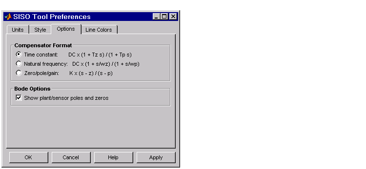
Selecting Format under Compensators activates the SISO Tool Preferences editor with the Options page open. This figure shows the Options page.

Use the radio buttons to toggle between time constant, natural frequency, and zero/pole/gain compensator formats.
By default, the SISO Design Tool shows the plant poles and zeros on Bode diagrams as red x's and o's, respectively. Uncheck the Show plant/sensor poles and zeros box to hide the plant and sensor poles and zeros.
For a general description of the SISO Tool Preferences editor, see SISO Design Tool Preferences" online in the Control System Toolbox documentation.
Choose C or F from Edit under the Compensators menu to open the Edit Compensator window for the compensator (C) or the prefilter (F), respectively. For example, this figure shows the selection of the compensator.


If you had chosen F, the Edit Compensator F window would have opened. Both windows have the same functionality.
You can use this window to inspect pole, zero, and gain data, and to edit this data using your keyboard (as opposed to graphically editing the compensator data). You have the following choices available from this window:
In the following sections, the descriptions of these tasks apply equally to the prefilter (F) and the compensator (C).
Adjusting the Gain. To change the compensator gain, enter the new value in the Gain field.
Changing the Format. You can see the poles and zeros either as complex numbers (Zero/Pole Location) or as damping ratio and natural frequency pairs (Damping/Natural Frequency). The default is Zero/Pole Location, which means that the window shows the numerical values. Use the Format menu to toggle between the two formats.
Adding Poles and Zeros. To add real poles to your compensators, click Add Real Pole. This action opens an empty field in the Poles panel. Specify the pole value in the field. To add a pair of complex poles, click Add Complex Pole. In this case, two fields appear: one for the real and another for the imaginary part of the poles. Note that you must specify the a negative sign for the real part of the pole if you want to specify a pair left-plane poles, but that the imaginary part is defined as +/-, so you do not have to specify the sign for that part.
If you specify the damping/natural frequency format, there is no distinction between the real and complex pole specifications. Clicking either button opens two fields: one for specifying the damping and another for the natural frequency. If you clicked Add Real Pole, you only need to specify the natural frequency since the Edit Compensator window automatically places a 1 in the damping field in this case.
Adding zeros is exactly the same; click Add Real Zero or Add Complex Zero and proceed as above.
Editing Poles and Zeros. You can change the pole locations or damping ratios/natural frequencies for existing poles and zeros by specifying new values in the appropriate fields. The SISO Design Tool automatically updates to reflect the changes.
Deleting Poles and Zeros. Whenever you add poles or zeros using the Edit Compensator window, a delete box appears to the left of the fields used to specify the pole/zero values. Check this box anytime you want to delete the pole or zero specified next to it.
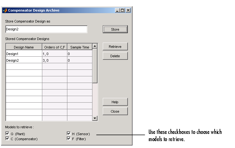
Use Store/Retrieve to open the Compensator Design Archive window.

To store a design, type a design name in the Store Compensator Design as field and click Store.
This window lists all the compensator designs you have stored during a SISO Design Tool session. It also lists the orders of your compensator (C) and prefilter (F) pairs, and their sample times (0 means that they're continuous).
To retrieve a stored design, left-click on the design name to select it and click Retrieve. To delete a design, select it and click the Delete button.
Clear
Select Clear to eliminate prefilter and compensator dynamics and set the gain to 1.

 | View | Analysis |  |