| Getting Started |
  |
Specifying Operating Conditions
If you have nonlinear components in your Simulink model, the Simulink LTI Viewer automatically linearizes them when you select Get Linearized Model. The Simulink LTI Viewer uses the initial state values you set in the Simulink diagram as default settings for linearization points for the states in the diagram. You also have the option to linearize about the operating conditions of your choice.
If you want your analysis model to be linearized about a zero state, or other state and input operating conditions, you must specify the desired operating points in the Operating Point dialog box before selecting Get Linearized Model.
To open the Operating Point dialog box, select Set Operating Point in the Simulink menu. This figure shows the open Operating Point dialog box.
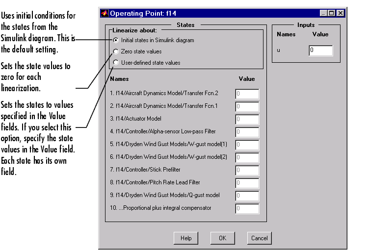
Figure 3-28: The Operating Point Dialog Box for Changing Linearization
Points
To change the default operating point behavior, follow these steps:
- Change the radio button selection (under Linearize about:) from the default to either:
- Set all state values for the linearization to zero
- Define your own state values for the linearization
- Use the fields under Value to specify the operating conditions for each input (and state) listed in the Operating Point window. You do not have to specify the states if you choose the Zero state values radio button.
- Once you have selected new operating conditions, click OK. This action opens a new dialog box, which is shown below.
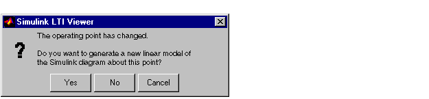
- Select Yes to finish the process.
Note the following:
- The inputs listed on the Operating Point window correspond to the Inport blocks on the top level of your Simulink model.
- All states and inputs in the Simulink diagram are listed in the Operating Point window, not just those associated with your analysis model.
- If you want to change the operating conditions, you need only change those values associated with your analysis model.
- While the Operating Point window is in the User-defined initial state values mode, the values listed in the window remain in effect throughout your Simulink LTI Viewer session unless you change these.
- While the Operating Point window is in the Initial state in Simulink diagram mode, the linearization values used by the Simulink LTI Viewer are updated as you change any state values in your Simulink diagram.
- To change the initial state values of your Simulink diagram:
- Select Parameters under the Simulation menu on your Simulink
diagram.
- Choose the Workspace I/O tab in the Simulation Parameters pane.
- Load initial states from the MATLAB workspace using the appropriate
field.
| | Bode Plots of Linearized Models | | Designing Compensators | |