| Getting Started | |
Bode Plots of Linearized Models
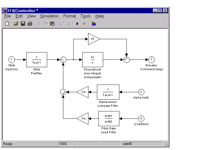
You can use the Simulink LTI Viewer to compare Bode plots for various controllers. For example, you can change the gain Ki in the F14 controller shown below and compare the Bode magnitudes.
Open-Loop Bode Response for the F14 Model
To specify open-loop analysis models, you must understand how Simulink performs linearization on the model. Placing the Input Point and Output Point blocks on your Simulink model does not break any connection or isolate any component.
For example, consider the following simple diagram.
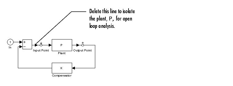
Based on the location of the Input Point and Output Point blocks, you might think that the analysis model specified by these blocks is simply the plant model, P. However, due to the feedback loop, this analysis model is actually the closed-loop transfer function  .
.
If you want to analyze the (open-loop) plant P instead, you need to open the loop, for example, by deleting the line between the Sum and Input Point blocks.
By default, the Simulink LTI Viewer performs closed-loop analysis whenever your diagram contains feedback loops between your Input and Output Point blocks. If you want an open loop Bode response plot, you must open the feedback path somewhere in the model by removing feedback lines.
In the F14 example, one way to create an open-loop model is to delete the feedback lines from pitch rate, q, and angle of attack, Alpha, back to the F14 controller. This figure shows the f14 model with the feedback paths deleted.
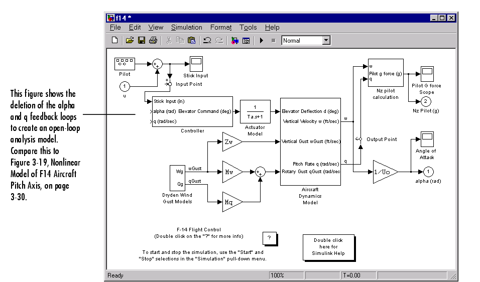
Figure 3-25: F14 Model with the Pitch Rate, q, and Angle of Attack, Alpha, Feedback Paths Removed
Once you have removed the feedback paths, you can proceed with open-loop analysis of your linearized model.
Comparing Bode Magnitudes in the Simulink LTI Viewer
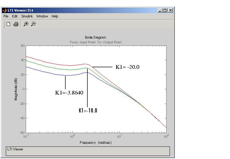
The Simulink LTI Viewer maintains a history of plots, so you can vary Ki in the controller and compare the changes in the Bode response. Each time you change Ki, select Get Linearized Model under the Simulink menu and the viewer will plot the new results. This figure shows the open-loop Bode magnitude for three values of Ki.
Figure 3-26: Open-Loop Bode Magnitudes for Three Values of K1
This example compares Bode magnitudes for several values of a parameter. You can, however, alter other elements of your analysis model for comparison. These elements include
Saving Analysis Models
The analysis models obtained each time you select Get Linearized Model are stored only in the Simulink LTI Viewer workspace. You can save these models into the main MATLAB workspace by selecting Export from the Simulink LTI Viewer File menu.
Selecting Export opens the window shown below.
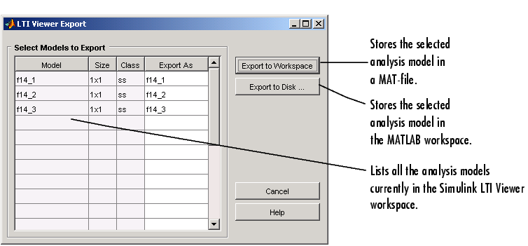
Figure 3-27: Exporting Analysis Models From the LTI Viewer Workspace
If you save models to a MAT-file, MATLAB prompts you to name the file. The variable names contained in that file are the same as those you selected from the Export List. The variable names of each model you save to the MATLAB workspace are also the same as those listed in the Export List. It's up to you to modify the names of these variables after you've saved them.
Removing Input Points and Output Points
There are two ways you can remove Input Point or Output Point blocks from the Simulink model:
When you delete an Input Point or an Output Point block, the signal lines coming into and out of this block are automatically reconnected.
| | Comparing Linear and Nonlinear Models | Specifying Operating Conditions | |