| Using Simulink | |
Editing Waveforms
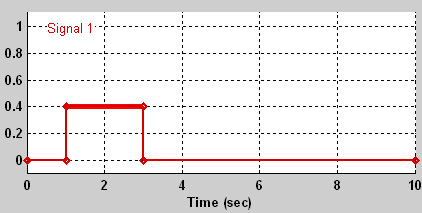
The Signal Builder dialog box allows you to change the shape, color, and line style and thickness of the signal waveforms output by a signal group.
Reshaping a Waveform
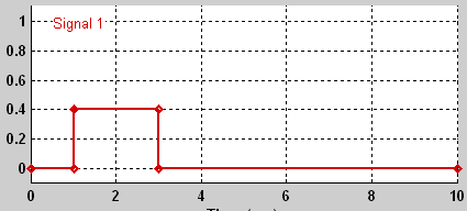
The Signal Builder dialog box allows you to change the shape of a waveform by selecting and dragging its line segments and points or by editing the coordinates of segments or points.
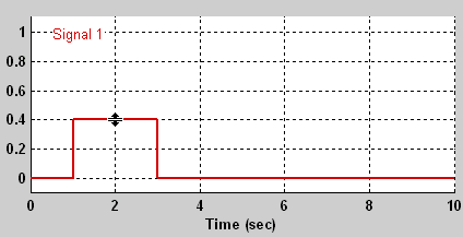
Selecting a Waveform. To select a waveform, left-click the mouse on any point on the waveform.
The Signal Builder displays the waveform's points to indicate that the waveform is selected.
To deselect a waveform, left-click any point on the waveform graph that is not on the waveform itself or press the Esc key.
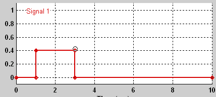
Selecting points. To select a point of a waveform, first select the waveform. Then position the mouse cursor over the point. The cursor changes shape to indicate that it is over a point.
Left-click the point with the mouse. The Signal Builder draws a circle around the point to indicate that it is selected.
To deselect the point, press the Esc key.
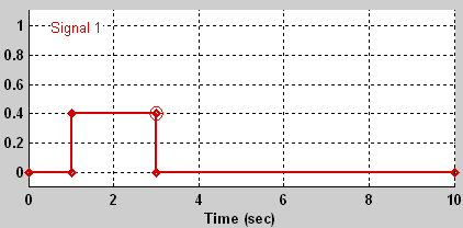
Selecting Segments. To select a line segment, first select the waveform that contains it. Then left-click the segment. The Signal Builder thickens the segment to indicate that it is selected.
To deselect the segment, press the Esc key.
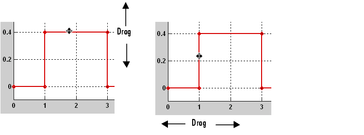
Dragging Segments. To drag a line segment to a new location, position the mouse cursor over the line segment. The mouse cursor changes shape to show the direction in which you can drag the segment.
Press the left mouse button and drag the segment in the direction indicated to the desired location.
Dragging points. To drag a point along the signal amplitude (vertical) axis, move the mouse cursor over the point. The cursor changes shape to a circle to indicate that you can drag the point. Drag the point parallel to the x-axis to the desired location. To drag the point along the time (horizontal) axis, press the Shift key while dragging the point.
Snap Grid. Each waveform axis contains an invisible snap grid that facilitates precise positioning of waveform points. The origin of the snap grid coincides with the origin of the waveform axis. When you drop a point or segment that you have been dragging, the Signal Builder moves the point or the segment's points to the nearest point or points on the grid, respectively. The Signal Builder's Axes menu allows you to specify the grid's horizontal (time) axis and vertical (amplitude) axis spacing independently. The finer the spacing, the more freedom you have in placing points but the harder it is to position points precisely. By default, the grid spacing is 0, which means that you can place points anywhere on the grid; i.e., the grid is effectively off. Use the Axes menu to select the spacing that you prefer.
Inserting and Deleting points. To insert a point, first select the waveform. Then hold down the Shift key and left-click the waveform at the point where you want to insert the point. To delete a point, select the point and press the Del key.
Editing Point Coordinates. To change the coordinates of a point, first select the point. The Signal Builder displays the current coordinates of the point in the Left Point edit fields at the bottom of the Signal Builder dialog box. To change the amplitude of the selected point, edit or replace the value in the y field with the new value and press Enter. The Signal Builder moves the point to its new location. Similarly edit the value in the t field to change the time of the selected point.
Editing Segment Coordinates. To change the coordinates of a segment, first select the segment. The Signal Builder displays the current coordinates of the endpoints of the segment in the Left Point and Right Point edit fields at the bottom of the Signal Builder dialog box. To change a coordinate, edit the value in its corresponding edit field and press Enter.
Changing the Color of a Waveform
To change the color of a signal waveform, select the waveform and then select Color from the Signal Builder's Signal menu. The Signal Builder displays the MATLAB color chooser. Choose a new color for the waveform. Click OK.
Changing a Waveform's Line Style and Thickness
The Signal Builder can display a waveform as a solid, dashed, or dotted line. It uses a solid line by default. To change the line style of a waveform, select the waveform, then select Line style from the Signal Builder's Signal menu. A menu of line styles pops up. Select a line style from the menu.
To change the line thickness of a waveform, select the waveform, then select Line width from the Signal menu. A dialog box appears with the line's current thickness. Edit the thickness value and click OK.
Signal Builder Time Range
The Signal Builder's time range determines the span of time over which its output is explicitly defined. By default, the time range runs from 0 to 10 seconds. You can change both the beginning and ending times of a block's time range (see Changing a Signal Builder's Time Range).
If the simulation starts before the start time of a block's time range, the block extrapolates its initial output from its first two defined outputs. If the simulation runs beyond the block's time range, the block by default outputs its final defined values for the remainder of the simulation. The Signal Builder's Simulation Options dialog box allows you to specify other final output options (see Signal values after final time for more information).
Changing a Signal Builder's Time Range
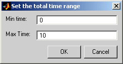
To change the time range, select Change time range from the Signal Builder's Axes menu. A dialog box appears.
Edit the Min. time and Max. time fields as necessary to reflect the beginning and ending times of the new time range, respectively. Click OK.
| | Editing Signals | Exporting Signal Group Data | |