
| Using Simulink |   |
Connecting Blocks
Simulink block diagrams use lines to represent pathways for signals among blocks in a model (see Annotating Diagrams for information on signals). Simulink can connect blocks for you or you can connect the blocks yourself by drawing lines from their output ports to their input ports.
Automatically Connecting Blocks
You can command Simulink to connect blocks automatically. This eliminates the need for you to draw the connecting lines yourself. When connecting blocks, Simulink routes lines around intervening blocks to avoid cluttering the diagram.
Connecting Two Blocks

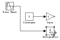
When connecting two blocks, Simulink draws as many connections as possible between the two blocks as illustrated in the following example.

Connecting Groups of Blocks
Simulink can connect a group of source blocks to a destination block or a source block to a group of destination blocks.
To connect a group of source blocks to a destination block:
To connect a source block to a group of destination blocks:
 | Enabling Sample Time Colors | Manually Connecting Blocks |  |