| Simulink Reference | |
Perform the specified logical operation on the input
Library
Simulink Math Operations and Fixed-Point Blockset Logic & Comparison
Description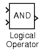
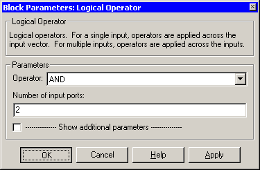
The Logical Operator block performs the specified logical operation on its inputs. An input value is TRUE (1) if it is nonzero and FALSE (0) if it is zero.
You select the Boolean operation connecting the inputs with the Operator parameter list. The block icon updates to display the selected operator. The supported operations are given below.
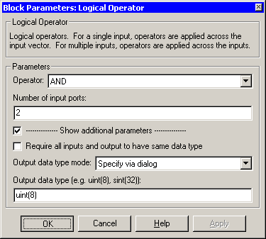
The number of input ports is specified with the Number of input ports parameter. The output type is specified with the Output data type mode and/or the Output data type parameters. An output value is 1 if TRUE and 0 if FALSE.
| Note The output data type should represent zero exactly. Data types that satisfy this condition include signed and unsigned integers, and any floating-point data type. |
The size of the output depends on input vector size and the selected operator:
If the block has more than one input, the output has the same dimensions as the inputs (after scalar expansion) and each output element is the result of applying the specified logical operation to the corresponding input elements. For example, if the specified operation is AND and the inputs are 2-by-2 arrays, the output is a 2-by-2 array whose top left element is the result of applying AND to the top left elements of the inputs, etc.
When configured as a multi-input XOR gate, this block performs an addition- modulo-two operation as mandated by the IEEE Standard for Logic Elements.
When the Show additional parameters check box is selected, some of the parameters that become visible are common to many blocks. For a detailed description of these parameters, refer to Block Parameters in the Fixed-Point Blockset documentation.
Data Type Support
A Logical Operator block accepts real or complex signals of any data type except int64 and uint64. However, if the Output data type mode parameter is set to Logical, the input may only be boolean or double.
Parameters and Dialog Box
Boolean, or choose to specify the data type through the Output data type parameter. Logical to have the output data type determined by the Boolean Logic Signals parameter in the Advanced tab of the Simulation Parameters Interface. If you select Logical and Boolean Logic Signals is on, then the output data type is always Boolean. If you select Logical and Boolean Logic Signals is off, then the output data type will match the input data type, which may be Boolean or double.Specify via dialog is selected for the Output data type mode parameter.Characteristics
| Dimensionalized |
Yes |
| Direct Feedthrough |
Yes |
| Sample Time |
Inherited from the driving block |
| Scalar Expansion |
Of inputs |
| Zero Crossing |
No |
| | Interpolation (n-D) Using PreLook-Up | Look-Up Table | |