| Simulink Reference | |
Check that a signal falls inside a range of amplitudes that varies from time step to time step.
Library
Description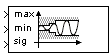
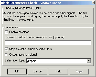
The Check Dynamic Range block checks that a test signal falls inside a range of amplitudes at each time step. The width of the range can vary from time step to time step. The input labeled sig is the test signal. The inputs labeled min and max are the lower and upper bounds of the valid range at the current time step. If the verification condition is true, the block does nothing. If not, the block halts the simulation, by default, and displays an error message.
The Check Dynamic Range block and its companion blocks in the Model Verification library are intended to facilitate creation of self-validating models. For example, you can use model verification blocks to test that signals do not exceed specified limits during simulation. When you are satisfied that a model is correct, you can turn error-checking off by disabling the verification blocks. You do not have to physically remove them from the model. If you need to modify a model, you can temporarily turn the verification blocks back on to ensure that your changes do not break the model.
Data Type Support
The Check Dynamic Range block accepts input signals of any dimensions and any built-in data type except int64 and uint64. All three input signals must have the same dimension and data type. If the inputs are nonscalar, the block checks each element of the input test signal to the corresponding elements of the reference signals.
Parameters and Dialog Box
1) at each time step if the assertion succeeds and false (0) if the assertion fails. The data type of the output signal is boolean if you have selected the Boolean logic signals option on the Advanced pane of Simulink's Simulation Parameters dialog box. Otherwise the data type of the output signal is double.graphic or text. The graphic option displays a graphical representation of the assertion condition on the icon. The text option displays a mathematical expression that represents the assertion condition. If the icon is too small to display the expression, the text icon displays an exclamation point. To see the expression, enlarge the icon.Characteristics
| Direct Feedthrough |
No |
| Sample Time |
Inherited from driving block |
| Scalar Expansion |
No |
| Dimensionalized |
Yes |
| Zero Crossing |
No |
| | Check Dynamic Lower Bound | Check Dynamic Upper Bound | |