| Getting Started | |
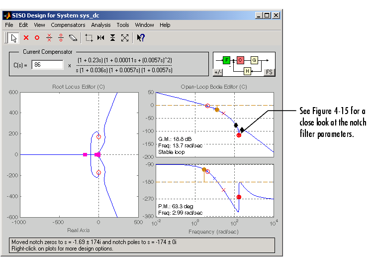
If you know that you have disturbances to your system at a particular frequency, you can use a notch filter to attenuate the gain of the system at that frequency. To add a notch filter, select Add Notch from the right-click menu and place the filter at the frequency you want to attenuate. A black `x' will appear next to the mouse arrow; place it at the frequency you want to attenuate.
Figure 4-18: The SISO Tool with a Notch Filter Added to the DC Motor Compensator
Note that to add the notch filter it was necessary to zoom out, since the notch frequency is at a higher frequency than Figure 4-15 displayed.
To see the notch filter parameters in more detail, select Zoom X-Y in the right-click menu for the Bode magnitude plot. Left-click and drag your mouse to draw a box around the notch filter. When you release the mouse, the SISO Design Tool will zoom in on the selected region.
This figure zooms in on the notch filter to show the adjustable parameters.
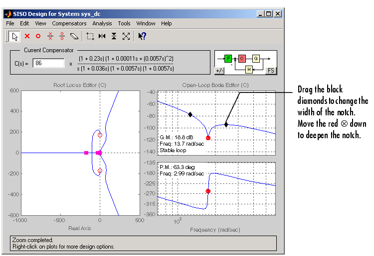
Figure 4-19: Manipulating Notch Filter Parameters
To understand how adjusting the notch filter parameters affects the filter, consider the notch filter transfer function.
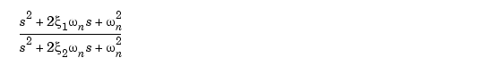
The three adjustable parameters are  1, 2, and
  n. The ratio of 2/1 sets the depth of the notch, and n is the natural frequency of the notch. This diagram shows how moving the red
  and black diamonds change these parameters, and hence the transfer function of the notch filter.
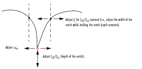
Figure 4-20: A Close Look at Notch Filter Parameters
| | Changing Units on a Plot | Adding a Prefilter | |