
| Getting Started |   |
Example: LQG Design
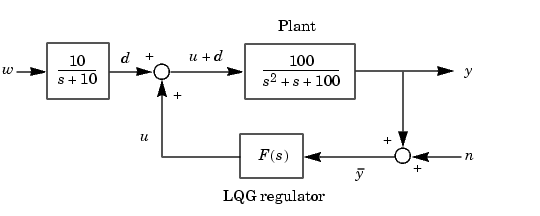
As an example of LQG design, consider the regulation problem illustrated below.

Figure 4-51: Simple Regulation Loop
The goal is to regulate the plant output  around zero. The input disturbance
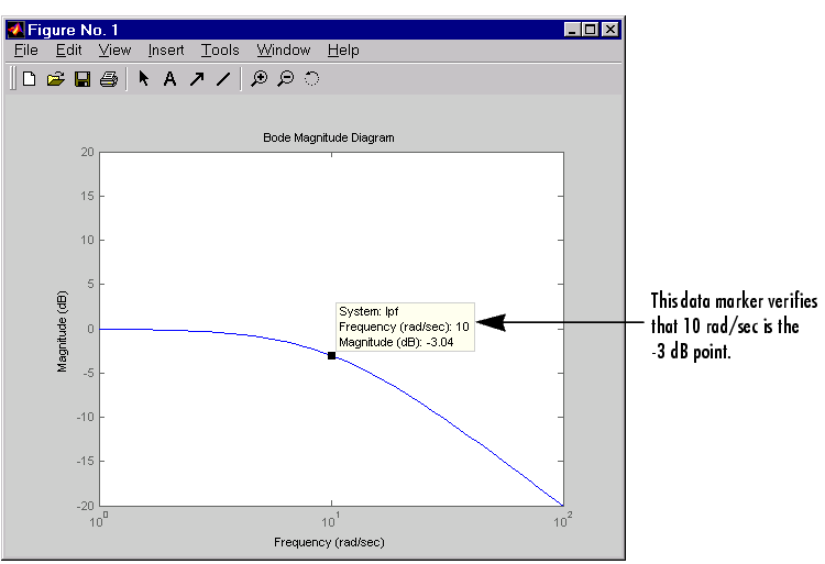
  is low frequency with power spectral density (PSD) concentrated below 10 rad/sec. For LQG design purposes, it is modeled as white noise driving a low-pass filter with a cutoff at 10 rad/sec, as this figure shows.

This figure shows the Bode magnitude of the shaping filter.

Figure 4-52: Bode Magnitude of the Low-Pass Filter
There is some measurement noise  , with noise intensity given by

to specify the trade-off between regulation performance and cost of control. Note that an open-loop state-space model is

where  is a state-space realization of
  .
.
The following commands design the optimal LQG regulator  for this problem.
sys = ss(tf(100,[1 1 100])) % State-space plant model

% Design LQ-optimal gain K
K = lqry(sys,10,1) % u = -Kx minimizes J(u)

% Separate control input u and disturbance input d
P = sys(:,[1 1]);
% input [u;d], output y

% Design Kalman state estimator Kest.
Kest = kalman(P,1,0.01)

% Form LQG regulator = LQ gain + Kalman filter.
F = lqgreg(Kest,K)
The last command returns a state-space model F of the LQG regulator  . Note that
 lqry, kalman, and lqgreg perform discrete-time LQG design when applied to discrete plants.
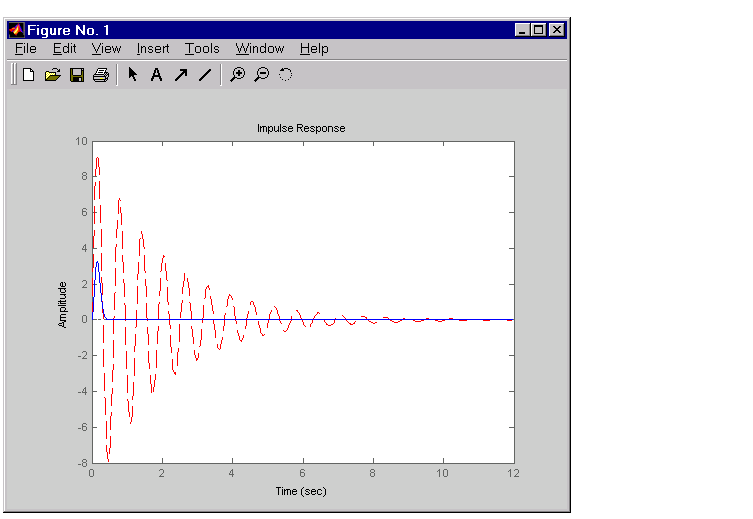
To validate the design, close the loop with feedback, create and add the lowpass filter in series with the closed-loop system, and compare the open- and closed-loop impulse responses by using the impulse function.
% Close loop
clsys = feedback(sys,F,+1)    % Note positive feedback.

% Create the lowpass filter and add it in series with clsys.
s = tf('s');
lpf= 10/(s+10) ;
clsys_fin = lpf*clsys;

% Open- vs. closed-loop impulse responses
impulse(sys,'r--',clsys_fin,'b-')
This figure compares the open- and closed-loop impulse responses for this example.

Figure 4-53: Comparison of Open- and Closed-Loop Impulse Response for the LQG Example
 | Linear-Quadratic-Gaussian (LQG) Design | Example: LQG Design for Set Point Tracking |  |