
| Design Case Studies |   |
Washout Filter Design
What you need to do is make sure the spiral mode does not move further into the left-half plane when you close the loop. One way flight control designers have addressed this problem is to use a washout filter  where
where

The washout filter places a zero at the origin, which constrains the spiral mode pole to remain near the origin. We choose  for a time constant of five seconds and use the root locus technique to select the filter gain
 H. First specify the fixed part  of the washout by
Connect the washout in series with the design model sys11 (relation between input 1 and output 1) to obtain the open-loop model
and draw another root locus for this open-loop model.
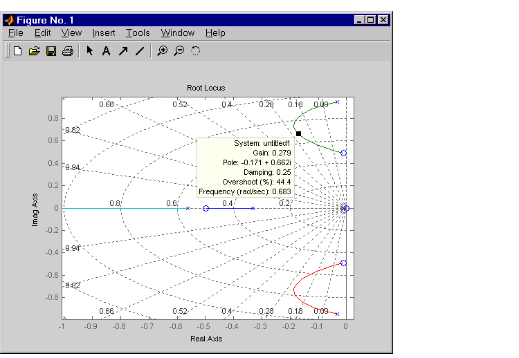
Create and drag a data marker around the upper curve to locate the maximum damping, which is about  .
.
This figure shows a data marker at the maximum damping ratio; the gain is approximately 2.07.

Look at the closed-loop response from rudder to yaw rate.
The response settles nicely but has less damping than your previous design. Finally, you can verify that the washout filter has fixed the spiral mode problem. First form the complete washout filter  (washout + gain).
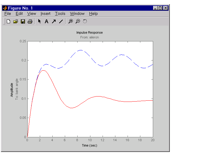
Then close the loop around the first I/O pair of the MIMO model sys and simulate the impulse response.
The bank angle response (output 2) due to an aileron impulse (input 2) now has the desired nearly constant behavior over this short time frame. To inspect the response more closely, use the I/O Selector in the right-click menu to select the (2,2) I/O pair.

Although you did not quite meet the damping specification, your design has increased the damping of the system substantially and now allows the pilot to fly the aircraft normally.
 | Root Locus Design | Hard-Disk Read/Write Head Controller |  |