| Using Simulink | |
The Workspace I/O Pane
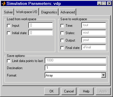
You can direct simulation output to workspace variables and get input and initial states from the workspace. On the Simulation Parameters dialog box, select the Workspace I/O tab. This pane appears.
Loading Input from the Base Workspace
Simulink can apply input from a model's base workspace to the model's top-level inports during a simulation run. To specify this option, select the Input box in the Load from workspace area of the Workspace I/O pane. Then, enter an external input specification (see below) in the adjacent edit box and select Apply.
The external (i.e., from workspace) input can take any of the following forms.
Array. To use this format, select Input in the Load from workspace pane and select the Array option from the Format list on the Workspace I/O pane. Selecting this option causes Simulink to evaluate the expression next to the Input check box and use the result as the input to the model.
The expression must evaluate to a real (noncomplex) matrix of data type double. The first column of the matrix must be a vector of times in ascending order. The remaining columns specify input values. In particular, each column represents the input for a different Inport block signal (in sequential order) and each row is the input value for the corresponding time point. Simulink linearly interpolates or extrapolates input values as necessary if the Interpolate data option is selected for the corresponding Inport.
The total number of columns of the input matrix must equal n + 1, where n is the total number of signals entering the model's inports.
The default input expression for a model is [t,u] and the default input format is Array. So if you define t and u in the base workspace, you need only select the Input option to input data from the model's base workspace. For example, suppose that a model has two inports, one of which accepts two signals and the other of which accepts one signal. Also, suppose that the base workspace defines u and t as follows.
Structure with time. Simulink can read data from the workspace in the form of a structure whose name is specified in the Input text field. The input structure must have two top-level fields: time and signals. The time field contains a column vector of the simulation times. The signals field contains an array of substructures, each of which corresponds to a model input port.
Each signals substructure must contain two fields named values and dimensions, respectively. The values field must contain an array of inputs for the corresponding input port where each input corresponds to a time point specified by the time field. The dimensions field specifies the dimensions of the input. If each input is a scalar or vector (1-D array) value, the dimensions field must be a scalar value that specifies the length of the vector (1 for a scalar). If each input is a matrix (2-D array), the dimensions field must be a two-element vector whose first element specifies the number of rows in the matrix and whose second element specifies the number of columns.
If the inputs for a port are scalar or vector values, the values field must be an M-by-N array where M is the number of time points specified by the time field and N is the length of each vector value. For example, the following code creates an input structure for loading 11 time samples of a two-element signal vector of type int8 into a model with a single input port.
a.time = (0:0.1:1)';
c1 = int8([0:1:10]');
c2 = int8([0:10:100]');
a.signals(1).values = [c1 c2];
a.signals(1).dimensions = 2;
To load this data into the model's inport, you would select the Input option on the Workspace I/O pane and enter a in the input expression field.
If the inputs for a port are matrices (2-D arrays), the values field must be an M-by-N-by-T array where M and N are the dimensions of each matrix input and T is the number of time points. For example, suppose that you want to input 51 time samples of a 4-by-5 matrix signal into one of your model's input ports. Then, the corresponding dimensions field of the workspace structure must equal [4 5] and the values array must have the dimensions 4-by-5-by-51.
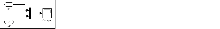
As another example, consider the following model, which has two inputs.
Suppose that you want to input a sine wave into the first port and a cosine wave into the second port. To do this, define a vector, a, as follows, in the base workspace.
a.time = (0:0.1:1)';
a.signals(1).values = sin(a.time);
a.signals(1).dimensions = 1;
a.signals(2).values = cos(a.time);
a.signals(2).dimensions = 1;
Select the Input box for this model, enter a in the adjacent text field, and select StructureWithTime as the I/O format.
| Note Simulink can read back simulation data saved to the workspace in the Structure with time output format. See Structure with time for more information. |
Structure. The Structure format is the same as the Structure with time format except that the time field is empty. For example, in the preceding example, you could set the time field as follows:
In this case, Simulink reads the input for the first time step from the first element of an inport's value array, the value for the second time step from the second element of the value array, etc.
| Note Simulink can read back simulation data saved to the workspace in the Structure output format. See Structure for more information. |
Per-Port Structures. This format consists of a separate structure-with-time or structure-without-time for each port. Each port's input data structure has only one signals field. To specify this option, enter the names of the structures in the Input text field as a comma-separated list, in1, in2, ..., inN, where in1 is the data for your model's first port, in2 for the second inport, and so on.
Time Expression.. The time expression can be any MATLAB expression that evaluates to a row vector equal in length to the number of signals entering the model's inports. For example, suppose that a model has one vector inport that accepts two signals. Furthermore, suppose that timefcn is a user-defined function that returns a row vector two elements long. The following are valid input time expressions for such a model.
Simulink evaluates the expression at each step of the simulation, applying the resulting values to the model's inports. Note that Simulink defines the variable t when it runs the simulation. Also, you can omit the time variable in expressions for functions of one variable. For example, Simulink interprets the expression sin as sin(t).
Saving Output to the Workspace
You can specify return variables by selecting the Time, States, and/or Output check boxes in the Save to workspace area of this dialog box pane. Specifying return variables causes Simulink to write values for the time, state, and output trajectories (as many as are selected) into the workspace.
To assign values to different variables, specify those variable names in the fields to the right of the check boxes. To write output to more than one variable, specify the variable names in a comma-separated list. Simulink saves the simulation times in the vector specified in the Save to Workspace area.
| Note Simulink saves the output to the workspace at the base sample rate of the model. Use a To Workspace block if you want to save output at a different sample rate. |
The Save options area enables you to specify the format and restrict the amount of output saved.
Format options for model states and outputs are listed below.
Array. If you select this option, Simulink saves a model's states and outputs in a state and output array, respectively.
The state matrix has the name specified in the Save to Workspace area (for example, xout). Each row of the state matrix corresponds to a time sample of the model's states. Each column corresponds to an element of a state. For example, suppose that your model has two continuous states, each of which is a two-element vector. Then the first two elements of each row of the state matrix contains a time sample of the first state vector. The last two elements of each row contain a time sample of the second state vector.
The model output matrix has the name specified in the Save to Workspace area (for example, yout). Each column corresponds to a model outport, each row to the outputs at a specific time.
Structure with time. If you select this format, Simulink saves the model's states and outputs in structures having the names specified in the Save to Workspace area (for example, xout and yout).
The structure used to save outputs has two top-level fields: time and signals. The time field contains a vector of the simulation times. The signals field contains an array of substructures, each of which corresponds to a model outport. Each substructure has four fields: values, dimensions, label, and blockName. The values field contains the outputs for the corresponding outport. If the outputs are scalars or vectors, the values field is a matrix each of whose rows represents an output at the time specified by the corresponding element of the time vector. If the outputs are matrix (2-D) values, the values field is a 3-D array of dimensions M-by-N-by-T where M-by-N is the dimensions of the output signal and T is the number of output samples. If T = 1, MATLAB drops the last dimension. Therefore, the values field is an M-by-N matrix. The dimensions field specifies the dimensions of the output signal. The label field specifies the label of the signal connected to the outport or the type of state (continuous or discrete). The blockName field specifies the name of the corresponding outport or block with states.
The structure used to save states has a similar organization. The states structure has two top-level fields: time and signals. The time field contains a vector of the simulation times. The signals field contains an array of substructures, each of which corresponds to one of the model's states. Each signals structure has four fields: values, dimension, label, and blockName. The values field contains time samples of a state of the block specified by the blockName field. The label field for built-in blocks indicates the type of state: either CSTATE (continuous state) or DSTATE (discrete state). For S-Function blocks, the label contains whatever name is assigned to the state by the S-Function block.
The time samples of a state are stored in the values field as a matrix of values. Each row corresponds to a time sample. Each element of a row corresponds to an element of the state. If the state is a matrix, the matrix is stored in the values array in column-major order. For example, suppose that the model includes a 2-by-2 matrix state and that Simulink logs 51 samples of the state during a simulation run. The values field for this state would contain a 51-by-4 matrix where each row corresponds to a time sample of the state and where the first two elements of each row correspond to the first column of the sample and the last two elements correspond to the second column of the sample.
Structure. This format is the same as the preceding except that Simulink does not store simulation times in the time field of the saved structure.
Per-Port Structures. This format consists of a separate structure-with-time or structure-without-time for each output port. Each output data structure has only one signals field. To specify this option, enter the names of the structures in the Output text field as a comma-separated list, out1, out2, ..., outN, where out1 is the data for your model's first port, out2 for the second inport, and so on.
Saving data to the workspace can slow down the simulation and consume memory. To avoid this, you can limit the number of samples saved to the most recent samples or you can skip samples by applying a decimation factor. To set a limit on the number of data samples saved, select the check box labeled Limit data points to last and specify the number of samples to save. To apply a decimation factor, enter a value in the field to the right of the Decimation label. For example, a value of 2 saves every other point generated.
Loading and Saving States
Initial conditions, which are applied to the system at the start of the simulation, are generally set in the blocks. You can override initial conditions set in the blocks by specifying them in the States area of this pane.
You can also save the final states for the current simulation run and apply them to a subsequent simulation run. This feature can be useful when you want to save a steady-state solution and restart the simulation at that known state. The states are saved in the format that you select in the Save options area of the Workspace I/O pane.
To save the final states (the values of the states at the termination of the simulation), select the Final State check box and enter a variable in the adjacent edit field.
To load states, select the Initial State check box and specify the name of a variable that contains the initial state values. This variable can be a matrix or a structure of the same form as is used to save final states. This allows Simulink to set the initial states for the current session to the final states saved in a previous session, using the Structure or Structure with time format.
If the check box is not selected or the state array is empty ([]), Simulink uses the initial conditions defined in the blocks.
| | The Simulation Parameters Dialog Box | The Diagnostics Pane | |