

| Getting Started | |
Adjusting the Bandwidth
Since the design requirements include a 0.5 second rise time, try setting the gain so that the DC crossover frequency is about 3 rad/sec. The rationale for setting the bandwidth to 3 rad/sec is that, to a first-order approximation, this should correspond to about a 0.33 second time constant.
To make the crossover easier to see, select Grid from the right-click menu. This creates a grid for the Bode magnitude plot. Left-click on the Bode magnitude plot and drag the curve until you see the curve crossing over the 0 dB line (on the y axis) at 3 rad/sec. This changes both the SISO Design Tool display and the LTI Viewer step response.
This figure shows the SISO Design Tool.
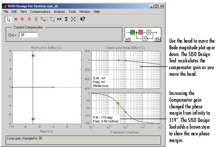
Figure 4-7: Root Locus and Bode Plots for the DC Motor
For a crossover at 3 rad/sec, the compensator gain should be about 38. By default, the SISO Design Tool displays gain and phase margin information in the lower left-hand corners of the Bode diagrams. In the Bode magnitude plot, it also tells you if your closed-loop system is stable or unstable.
This plot shows the associated closed-loop step response in the LTI Viewer.
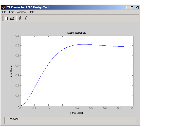
Figure 4-8: Closed-Loop Step Response for the DC Motor with a Compensator Gain = 38
The step response shows that the steady-state error and rise time have improved somewhat, but you must design a more sophisticated controller to meet all the design specifications, in particular, the steady-state error requirement.
| | Adjusting the Compensator Gain | Adding an Integrator | |