
| Getting Started |   |
Adding an Integrator
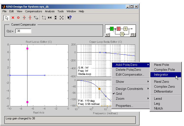
One way to eliminate steady-state error is to add an integrator. To do this, select Add Pole/Zero and then Integrator from the right-click menu. This figure shows the process.

Figure 4-9: Using the Right-Click Menu to Add an Integrator
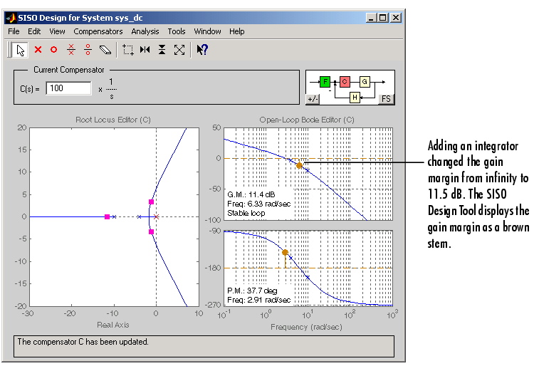
Notice adding the integrator changed the crossover frequency of the system. Readjust the compensator gain to bring the crossover back to 3 rad/sec; the gain should be about 100.
Once you have added the integrator and readjusted the compensator gain, the SISO Design Tool shows a red `x' at the origin of the root locus plot.

Figure 4-10: The SISO Design Tool Displays the Integrator on the Root Locus Plot
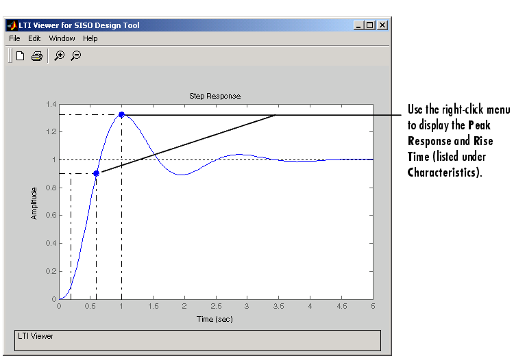
This figure shows the closed-loop step response.

Figure 4-11: The Step Response for the DC Motor with an Integrator in the Compensator
The step response is settling around 1, which satisfies the steady-state error requirement. This is because the integrator forces the system to zero steady-state error. The figure shows, however, that the peak response is 1.3, or about 30% overshoot, and that the rise time is roughly 0.4 second. So a compensator consisting of an integrator and a gain is not enough to satisfy the design requirements, which require that the overshoot be less than 10%.
 | Adjusting the Bandwidth | Adding a Lead Network |  |