| Design Case Studies | |
MIMO LQG Design
Start with the complete two-axis state-space model Pc derived above. The model inputs and outputs are
Pc.inputname

ans =
    'u-x'
    'u-y'
    'w-ex'
    'w-ix'
    'w_ey'
    'w_iy'

P.outputname

ans =
    'x-gap'
    'y-gap'
    'x-force'
    'y-force'
As earlier, add low-pass filters in series with the 'x-gap' and 'y-gap' outputs to penalize only low-frequency thickness variations.
Next, design the LQ gain and state estimator as before (there are now two commands and two measurements).
k = lqry(Pdes(1:2,1:2),eye(2),1e-4*eye(2))     % LQ gain
est = kalman(Pdes(3:4,:),eye(4),1e3*eye(2))    % Kalman estimator

RegMIMO = lqgreg(est,k)    % form MIMO LQG regulator
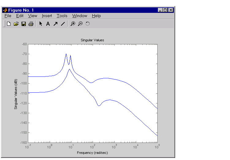
The resulting LQG regulator RegMIMO has two inputs and two outputs.
Plot its singular value response (principal gains).
Next, plot the open- and closed-loop time responses to the white noise inputs (using the MIMO LQG regulator for feedback).
% Form the closed-loop model
cl = feedback(Pc,RegMIMO,1:2,3:4,+1);

% Simulate with lsim using same noise inputs
lsim(Pc(1:2,3:6),':',cl(1:2,3:6),'-',wxy,t)
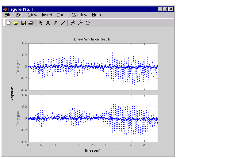
The MIMO design is a clear improvement over the separate SISO designs for each axis. In particular, the level of  /
/ thickness variation is now comparable to that obtained in the decoupled case. This example illustrates the benefits of direct MIMO design for multivariable systems.
| | Cross-Coupling Between Axes | Kalman Filtering | |