
| Tool and Viewer Reference |   |
Tools
Loop Responses
For examples that use LTI Viewers linked with the SISO Design Tool, see Designing Compensators in Getting Started with the Control System Toolbox. See the LTI Viewer for a complete description of all the features of the LTI Viewer.
Continuous/Discrete Conversions
Selecting Continuous/Discrete Conversions opens the Continuous/Discrete Conversions window, which you can use to convert between continuous to discrete designs.You can select the following:
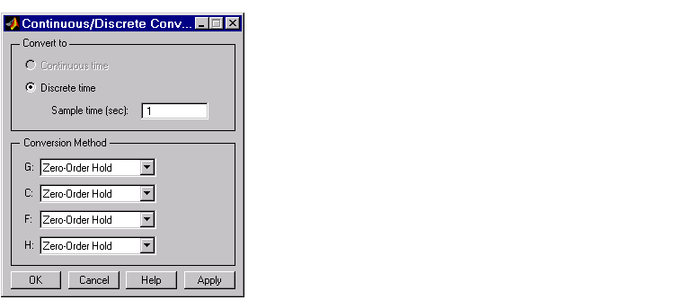
This picture shows the window.

The Continuous/Discrete Conversion Window
Conversion domain. If your current model is continuous-time, the upper panel of the Continuous/Discrete Conversion window automatically selects the Discrete time radio button. If your model is in discrete-time, see Discrete-time domain.
To convert to discrete time, you must specify a positive number for the sample time in the Sample time (sec) field.
You can perform continuous to discrete conversions on any of the components of your model: the plant (G), the compensator (C), the prefilter (F), or the sensor (H). Select the method you want to use from the menus next to the model elements.
Conversion method. The following are the available continuous-to-discrete conversion methods:
If you choose Tustin with prewarping, you must specify the critical frequency in rad/sec.
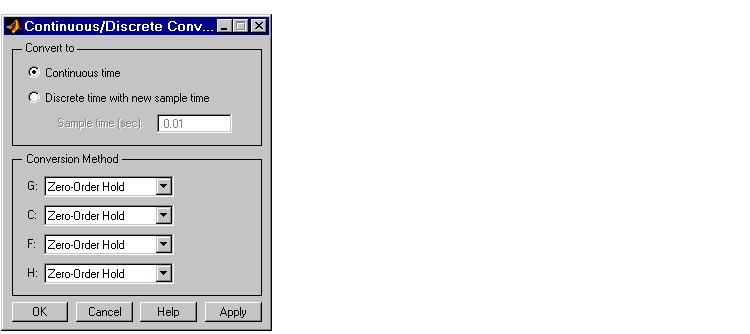
Discrete-time domain. If you currently have a discrete-time system, the Continuous/Discrete Conversion window looks like this figure.

You can either change the sample time of the discrete system (resampling) or do a discrete-to-continuous conversion.
To resample your system, select Discrete time with new sample time and specify the new sample time in the Sample time (sec) field. The sample time must be a positive number.
To convert from discrete-time to continuous-time, you have the following options for the conversion method:
Again, if you choose Tustin with prewarping, you must specify the critical frequency.
Draw Simulink Diagram
| Note You must have a license for Simulink to use this feature. If you do not have Simulink, you will not see this option under the Tools menu. |
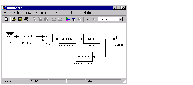
Select Draw Simulink Diagram to draw a block diagram of your system (plant, compensator, prefilter, and sensor). For the DC motor example described in Getting Started with the Control System Toolbox, this picture is the result.

 | Analysis | Window |  |