| Stateflow |
  |
Create a Stateflow Diagram
The following steps describe how to create a simple Stateflow diagram using the graphics editor:
- Double-click the Stateflow block in the Simulink model window to invoke the graphics editor window.

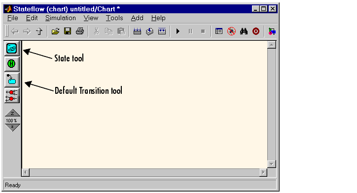
- Select the State button in the toolbar (see preceding graphic).
- Move the cursor into the drawing area and left-click to place the state.
- Position the cursor over that state, click the right mouse button, and drag to another location in the drawing area to make a copy of the state. Release the right mouse button to drop the state at that location.
- Click the ? character within each state to enter each state label.
- Label the states with the titles
Power_on and Power_off.
- Deselect the state to exit the edit.
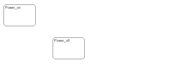
- To deselect a state, click anywhere outside the state or press the Esc key. Your Stateflow diagram should look similar to the following:

- Draw a transition starting from
Power_on and ending at Power_off by first placing the cursor at a straight portion of the border of the Power_on state. When the cursor changes to crosshairs, click-drag the mouse to the border of the Power_off state. When the transition snaps to the border of the Power_off state, release the mouse button.
- The crosshairs do not appear if you place the cursor on a corner, since corners are used for resizing.
- Draw another transition starting from
Power_off and ending on Power_on.
- Your Stateflow diagram should look similar to this sample.

- Label the transition from
Power_on to Power_off by first clicking the transition to select it. Click the ? character that appears alongside the transition and enter the label Switch. Press the Escape key to deselect the transition label and exit edit mode for this label.
- Label the transition from
Power_off to Power_on with the same text, Switch.
- Your Stateflow diagram should look similar to this sample.

- Add a default transition by selecting the Default Transition tool (see preceding graphic in step 1) in the toolbar and dragging the mouse to a straight portion on the border of the
Power_off state. Click and release the mouse when the arrowhead snaps to the border of the Power_off state. Your Stateflow diagram should look similar to this sample.

| Note
For more information on creating Stateflow diagrams using the graphics editor, see Working with Charts.
|
 | Create a Simulink Model | | Define Input Events |  |


