
| Tool and Viewer Reference |   |
The SISO Design Tool is a graphical-user interface (GUI) that allows you to use root-locus, Bode diagram, and Nichols plot techniques to design compensators. The SISO Design Tool by default displays the root locus and Bode diagrams for your imported systems. The two are dynamically linked; for example, if you change the gain in the root locus, it immediately affects the Bode diagrams as well.
This tool is used extensively in Getting Started with the Control System Toolbox. In particular, you should read Chapter 4, "Designing Compensators," of that book to see how to do typical design tasks with the SISO Design Tool. This document, on the other hand, is a reference that describes all available options for the SISO Design Tool.
Opening the SISO Design Tool
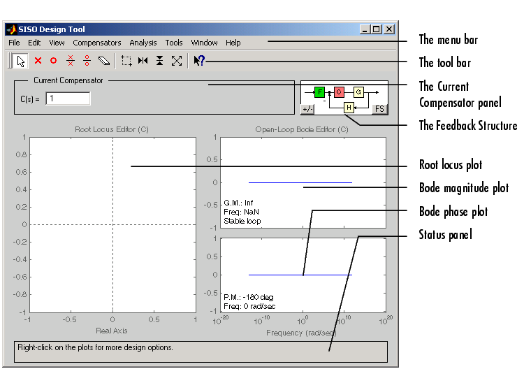
This picture shows the GUI and introduces some terminology.

This document describes the SISO Design Tool features left-to-right and top-to-bottom, starting with the menu bar and ending with the status panel at the bottom of the window.
If you want to match the SISO Design Tool pictures shown below, type
at the MATLAB prompt. This loads the same set of linear models that this document uses as examples in the GUI. The examples all use the Gservo system for plot displays.
 | Tool and Viewer Reference | Menu Bar |  |