| Using Simulink | |
Changing a Block's Appearance
The Simulink Editor allows you to change the size, orientation, color, and label location of a block in a block diagram.
Changing the Orientation of a Block
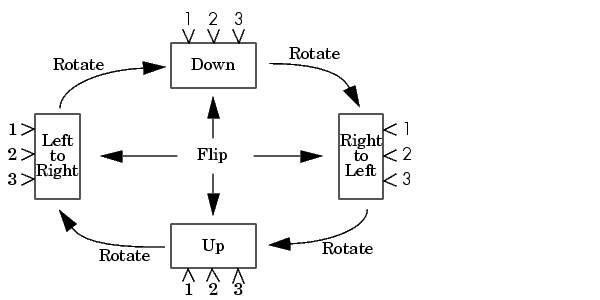
By default, signals flow through a block from left to right. Input ports are on the left, and output ports are on the right. You can change the orientation of a block by choosing one of these commands from the Format menu:
The figure below shows how Simulink orders ports after changing the orientation of a block using the Rotate Block and Flip Block menu items. The text in the blocks shows their orientation.
Resizing a Block's Icon
To change the size of a block, select it, then drag any of its selection handles. While you hold down the mouse button, a dotted rectangle shows the new block size. When you release the mouse button, the block is resized.
For example, the figure below shows a Signal Generator block being resized. The lower-right handle was selected and dragged to the cursor position. When the mouse button is released, the block takes its new size.
This figure shows a block being resized.
Displaying Parameters Beneath a Block's Icon
You can cause Simulink to display one or more of a block's parameters beneath the block's icon in a block diagram. You specify the parameters to be displayed in the following ways:
AttributesFormatString property to the format string, using set_param
Using Drop Shadows
You can add a drop shadow to a block by selecting the block, then choosing Show Drop Shadow from the Format menu. When you select a block with a drop shadow, the menu item changes to Hide Drop Shadow. The figure below shows a Subsystem block with a drop shadow.
| | Block Properties Dialog Box | Manipulating Block Names | |