
| Simulink Reference |   |
Implement a linear transfer function
Library
Description
The Transfer Fcn block implements a transfer function where the input (u) and output (y) can be expressed in transfer function form as the following equation

where nn and nd are the number of numerator and denominator coefficients, respectively. num and den contain the coefficients of the numerator and denominator in descending powers of s. num can be a vector or matrix, den must be a vector, and both are specified as parameters on the block dialog box. The order of the denominator must be greater than or equal to the order of the numerator.
A Transfer Fcn block takes a scalar input. If the numerator of the block's transfer function is a vector, the block's output is also scalar. However, if the numerator is a matrix, the transfer function expands the input into an output vector equal in width to the number of rows in the numerator. For example, a two-row numerator results in a block with scalar input and vector output. The width of the output vector is two.
Initial conditions are preset to zero. If you need to specify initial conditions, convert to state-space form using tf2ss and use the State-Space block. The tf2ss utility provides the A, B, C, and D matrices for the system. For more information, type help tf2ss or consult the Control System Toolbox documentation.
Transfer Fcn Block Icon
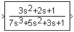
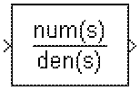
The numerator and denominator are displayed on the Transfer Fcn block icon depending on how they are specified:
[3,2,1] and Denominator as (den) where den is [7,5,3,1], the block icon looks like this:
(s). For example, if you specify Numerator as num and Denominator as den, the block icon looks like this:
Specifying the Absolute Tolerance for the Block's States
By default Simulink uses the absolute tolerance value specified in the Simulation Parameters dialog box (see Error Tolerances) to solve the states of the Transfer Fcn block. If this value does not provide sufficient error control, specify a more appropriate value in the Absolute tolerance field of the Transfer Fcn block's dialog box. The value that you specify is used to solve all the block's states.
Data Type Support
A Transfer Fcn block accepts and outputs signals of type double.
Parameters and Dialog Box
[1].[1 1].auto or a numeric value. If you enter auto, Simulink determines the absolute tolerance (see "Error Tolerances"). If you enter a numeric value, Simulink uses the specified value to solve the block's states. Note that a numeric value overrides the setting for the absolute tolerance in the Simulation Parameters dialog box.Characteristics
 | To Workspace | Transport Delay |  |