
| Simulink Reference |   |
Combine multiple signals into a single signal
Library
Description
The Merge block combines its inputs into a single output line whose value at any time is equal to the most recently computed output of its driving blocks. You can specify any number of inputs by setting the block's Number of inputs parameter.
| Note Merge blocks facilitate creation of alternately executing subsystems. See Creating Alternately Executing Subsystems for an application example. |
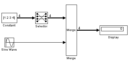
A Merge block does not accept signals whose elements have been reordered. For example, in the following diagram, the Merge block does not accept the output of the Selector block because the Selector block interchanges the first and fourth elements of the vector signal.

If the Allow unequal port widths parameter is not selected, the block accepts only inputs of equal dimensions and outputs a signal of the same dimensions as the inputs. If the Allow unequal port widths option is selected, the block accepts scalars and vectors (but not matrices) having differing numbers of elements. Further, the block allows you to specify an offset for each input signal relative to the beginning of the output signal. The width of the output signal is
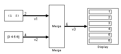
where w1, ... wn are the widths of the input signals and o1, ... on are the offsets for the input signals. For example, the Merge block in the following diagram merges signals v1 and v2 to produce signal v3. 
In this example, the offset of v1 is 0 and the offset of v2 is 2, resulting in an output signal six elements wide. The Merge block maps the elements of v1 to the first two elements of v3 and the elements of v2 to the last four elements of v3.
You can specify an initial output value by setting the block's Initial output parameter. If you do not specify an initial output and one or more of the driving blocks do, the Merge block's initial output equals the most recently evaluated initial output of the driving blocks.
Merging S-Function Outputs
The Merge block does can merge a signal from an S-Function block only if the memory used to store the S-Function block's output is reusable. Simulink displays an error message if you attempt to update or simulate a model that connects a nonreusable port of an S-Function block to a Merge block. See ssSetOutputPortReusable for more information.
Muxing Signals to be Merged
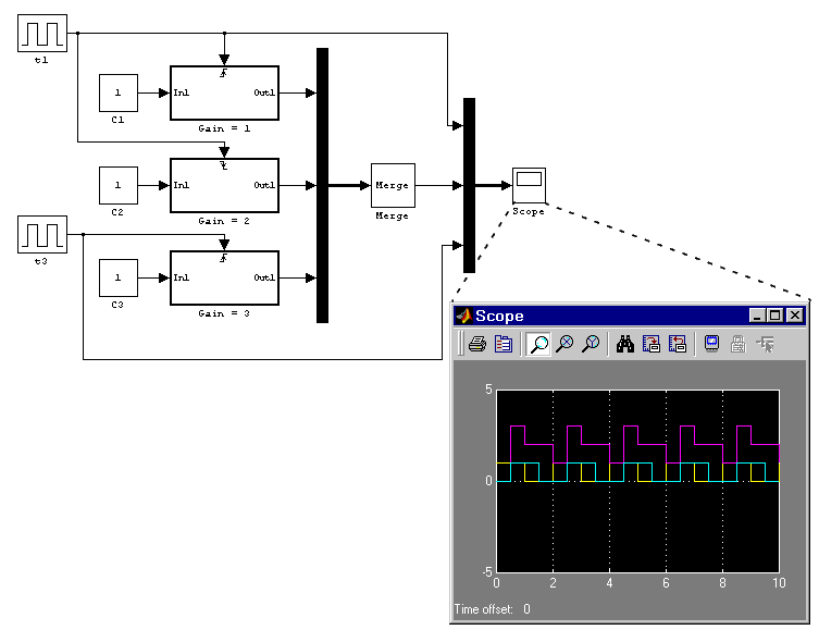
Instead of connecting signals directly to a Merge block, you can connect them via a Mux block as illustrated in the following example.

This example connects three amplifiers to a Merge block via a Mux block. The top and bottom amplifiers trigger on a rising pulse; the middle, on a falling pulse. The trigger signal connected to the bottom amplifier has a phase delay of .5 s compared to the trigger signal connected to the bottom amplifier. The output of the Merge block at each time step equals that of the amplifier triggered at that time step. Muxing the signals to be merged rather than connecting them directly to the Merge block can result in a clearer diagram.
Data Type Support
A Merge block accepts signals of any complexity and data type, including fixed-point data types, except int64 and uint64.
Parameters and Dialog Box
Characteristics
| Dimensionalized |
Yes |
| Direct Feedthrough |
Yes |
| Sample Time |
Inherited from the driving block |
| Scalar Expansion |
No |
| Zero Crossing |
No |
 | Memory | MinMax |  |