
| Simulink Reference |   |
Perform discrete-time integration of a signal
Library
Description
The Discrete-Time Integrator block can be used in place of the Integrator block to create a purely discrete system.
The Discrete-Time Integrator block allows you to
These features are described below.
Integration Methods
The block can integrate using these methods: Forward Euler, Backward Euler, and Trapezoidal. For a given step k, Simulink updates y(k) and x(k+1). T is the sampling period (delta T in the case of triggered sampling time). Values are clipped according to upper or lower limits. In all cases, y(0)=x(0)=IC (clipped if necessary), i.e., the initial output of the block is always the initial condition.
1/s is approximated by T/(z-1). The resulting expression for the output of the block at step k is
Let x(k+1) = x(k) + T*u(k). The block uses the following steps to compute its output:
Step 0:     y(0)   = x(0) = IC (clip if necessary)
            x(1)   = y(0) + T*u(0)

Step 1:     y(1)   = x(1)
            x(2)   = x(1) + T*u(1)

Step k:     y(k)   = x(k)
            x(k+1) = x(k) + T*u(k) (clip if necessary)
With this method, input port 1 does not have direct feedthrough.
1/s is approximated by T*z/(z-1). The resulting expression for the output of the block at step k is
Let x(k) = y(k-1). The block uses the following steps to compute its output:
T is fixed (equal to the sampling period), let
The block uses the following steps to compute its output:
Step 0:     y(0)   = x(0) = IC (clipped if necessary)
            x(1)   = y(0) + T/2 * u(0)

Step 1:     y(1)   = x(1) + T/2 * u(1)
            x(2)   = y(1) + T/2 * u(1)

Step k:     y(k)   = x(k) + T/2 * u(k)
            x(k+1) = y(k) + T/2 * u(k)
Here, x(k+1) is the best estimate of the next output. It isn't quite the state, in the sense that x(k) != y(k).
If T is variable (i.e. obtained from the triggering times), the block uses the following algorithm to compute its outputs:
The block icon reflects the selected integration method, as this figure shows.![]()
Defining Initial Conditions
You can define the initial conditions as a parameter on the block dialog box or input them from an external signal:
internal and enter the value in the Initial condition parameter field.
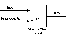
external. An additional input port appears under the block input, as shown in this figure.
Using the State Port
In two situations, you must use the state port instead of the output port:
bounce model.
clutch model.
You can correct these problems by passing the state through the state port rather than the output port. Although the values are the same, Simulink generates them at slightly different times, which protects your model from these problems. You output the block state by selecting the Show state port check box.
By default, the state port appears on the top of the block, as shown in this figure.
Limiting the Integral
To prevent the output from exceeding specifiable levels, select the Limit output check box and enter the limits in the appropriate parameter fields. Doing so causes the block to function as a limited integrator. When the output reaches the limits, the integral action is turned off to prevent integral wind up. During a simulation, you can change the limits but you cannot change whether the output is limited. The output is determined as follows:
To generate a signal that indicates when the state is being limited, select the Show saturation port check box. A saturation port appears below the block output port, as shown in this figure.
The signal has one of three values:
When the Limit output option is selected, the block has three zero crossings: one to detect when it enters the upper saturation limit, one to detect when it enters the lower saturation limit, and one to detect when it leaves saturation.
Resetting the State
The block can reset its state to the specified initial condition, based on an external signal. To cause the block to reset its state, select one of the External reset choices. A trigger port appears below the block's input port and indicates the trigger type, as shown in this figure.
rising to trigger the state reset when the reset signal has a rising edge.
falling to trigger the state reset when the reset signal has a falling edge.
either to trigger the reset when either a rising or falling signal occurs.
level to trigger the reset and hold the output to the initial condition while the reset signal is nonzero.
The reset port has direct feedthrough. If the block output is fed back into this port, either directly or through a series of blocks with direct feedthrough, an algebraic loop results. To resolve this loop, feed the output of the block's state port into the reset port instead. To access the block's state, select the Show state port check box.
Choosing All Options
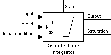
When all options are selected, the icon looks like this.
Data Type Support
A Discrete-Time Integrator block accepts and outputs real signals of type double.
Parameters and Dialog Box
ForwardEuler.rising, falling, either, level) occurs in the reset signal.internal) or from an external block (if set to external).internal.inf.-inf.1. See Specifying Sample Time in the online documentation for more information.Characteristics
 | Discrete State-Space | Discrete Transfer Fcn |  |