| Getting Started | |
Loop Responses
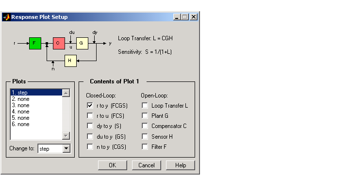
As you iterate on a compensator design, you may find it convenient to be able to examine the various loop responses (for example, step or impulse responses). To view, for example, the closed-loop step response, select Other Loop Response from the Analysis menu. This opens the Response Plot Setup window with the default setting of closed-loop step response from r, the reference signal, to y, the output signal.
Click OK to open an LTI Viewer with the closed-loop step response of the DC motor. For instructions on how to operate the LTI Viewer, see LTI Viewer.
This figure shows the resulting plot.
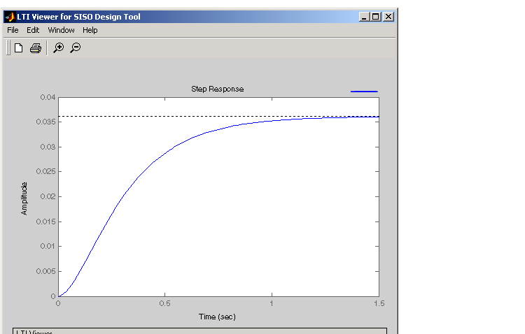
Figure 4-5: LTI Viewer Showing the Step Response for the DC Motor
As this plot shows, the step response of the DC motor is about 1.5 seconds, which is too slow for many applications. Also, there is a large steady-state error. The following sections show how to use Bode diagram techniques for improving the response time and steady-state error of the DC motor step response.
As you iterate on a design, the LTI Viewer associated with your SISO Design Tool will automatically update the response plots you have chosen.
| | Feedback Structure | Bode Diagram Design | |