

| Design Case Studies |   |
Process and Disturbance Models
The rolling mill is used to shape rectangular beams of hot metal. The desired outgoing shape is sketched below.
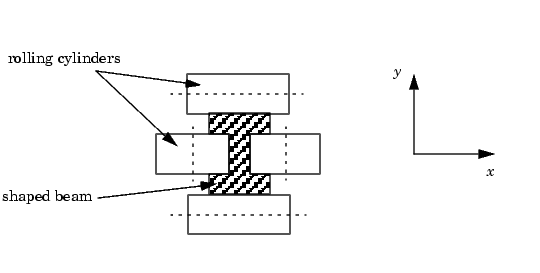
This shape is impressed by two pairs of rolling cylinders (one per axis) positioned by hydraulic actuators. The gap between the two cylinders is called the roll gap.
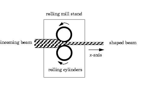
The objective is to maintain the beam thickness along the x- and y-axes within the quality assurance tolerances. Variations in output thickness can arise from the following:
Feedback control is necessary to reduce the effect of these disturbances. Because the roll gap cannot be measured close to the mill stand, the rolling force is used instead for feedback.
The input thickness disturbance is modeled as a low pass filter driven by white noise. The eccentricity disturbance is approximately periodic and its frequency is a function of the rolling speed. A reasonable model for this disturbance is a second-order bandpass filter driven by white noise.
This leads to the following generic model for each axis of the rolling process.
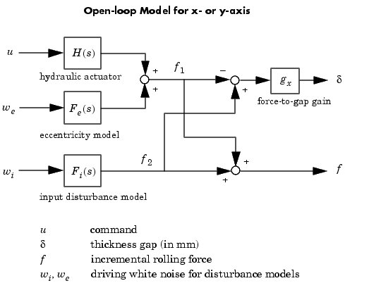
The measured rolling force variation  is a combination of the incremental force delivered by the hydraulic actuator and of the disturbance forces due to eccentricity and input thickness variation. Note that:
 , and
, and  are the incremental forces delivered by each component.
 .
.
The model data for each axis is summarized below.
Model Data for the x-Axis
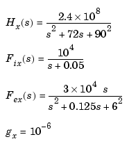
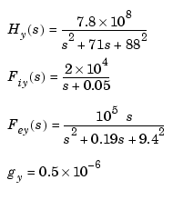
Model Data for the y-Axis
 | LQG Regulation: Rolling Mill Example | LQG Design for the x-Axis |  |