
| Simulink Reference |   |
Model the behavior of a system with play
Library
Description
The Backlash block implements a system in which a change in input causes an equal change in output. However, when the input changes direction, an initial change in input has no effect on the output. The amount of side-to-side play in the system is referred to as the deadband. The deadband is centered about the output. This figure shows the block's initial state, with the default deadband width of 1 and initial output of 0.

A system with play can be in one of three modes:
If the initial input is outside the deadband, the Initial output parameter value determines whether the block is engaged in a positive or negative direction, and the output at the start of the simulation is the input plus or minus half the deadband width.
For example, the Backlash block can be used to model the meshing of two gears. The input and output are both shafts with a gear on one end, and the output shaft is driven by the input shaft. Extra space between the gear teeth introduces play. The width of this spacing is the Deadband width parameter. If the system is disengaged initially, the output (the position of the driven gear) is defined by the Initial output parameter.
The following figures illustrate the block's operation when the initial input is within the deadband. The first figure shows the relationship between the input and the output while the system is in disengaged mode (and the default parameter values are not changed).

The next figure shows the state of the block when the input has reached the end of the deadband and engaged the output. The output remains at its previous value.

The final figure shows how a change in input affects the output while they are engaged.

If the input reverses its direction, it disengages from the output. The output remains constant until the input either reaches the opposite end of the deadband or reverses its direction again and engages at the same end of the deadband. Now, as before, movement in the input causes equal movement in the output.
For example, if the deadband width is 2 and the initial output is 5, the output, y, at the start of the simulation is as follows:
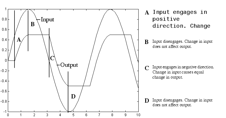
This sample model and the plot that follows it show the effect of a sine wave passing through a Backlash block.
The Backlash block parameters are unchanged from their default values (the deadband width is 1 and the initial output is 0). Notice in the plotted output following that the Backlash block output is zero until the input reaches the end of the deadband (at 0.5). Now the input and output are engaged and the output moves as the input does until the input changes direction (at 1.0). When the input reaches 0, it again engages the output at the opposite end of the deadband.

Data Type Support
A Backlash block accepts and outputs real values of type double.
Parameters and Dialog Box
1.0.Characteristics
| Direct Feedthrough |
Yes |
| Sample Time |
Inherited from driving block |
| Scalar Expansion |
Yes |
| Dimensionalized |
Yes |
| Zero Crossing |
Yes, if Enable zero crossing detection is selected. |
 | Assignment | Band-Limited White Noise |  |