
| Creating and Manipulating Models |   |
Simulink Block for LTI Systems
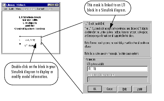
You can incorporate LTI objects into Simulink diagrams using the LTI System block shown below.

The LTI System block can be accessed either by typing
at the MATLAB prompt or by selecting Control System Toolbox from the Blocksets and Toolboxes section of the main Simulink library.
The LTI System block consists of the dialog box shown on the right in the figure above. In the editable text box labeled LTI system variable, enter either the variable name of an LTI object located in the MATLAB workspace (for example, sys) or a MATLAB expression that evaluates to an LTI object (for example, tf(1,[1 1])). The LTI System block accepts both continuous and discrete LTI objects in either transfer function, zero-pole-gain, or state-space form. Simulink converts the model to its state-space equivalent prior to initializing the simulation.
Use the editable text box labeled Initial states to enter an initial state vector for state-space models. The concept of "initial state" is not well-defined for transfer functions or zero-pole-gain models, as it depends on the choice of state coordinates used by the realization algorithm. As a result, you cannot enter nonzero initial states when you supply TF or ZPK models to LTI blocks in a Simulink diagram.