
| Getting Started |   |
Editing Compensator Pole and Zero Locations
A quick way to change poles and zeros is simply to grab them with your mouse and move them around the root locus plot region. If you want to specify precise numerical values, however, you should use the Edit Compensator window to change the gain value and the pole and zero locations of your compensator.
There are three ways to open the Edit Compensator window from the SISO Design Tool:
Whichever method you choose, the following window appears.

Figure 4-34: Use the Edit Compensator Window to Add, Delete and Move Compensator Poles and Zeros
You can use the Edit Compensator window to
For this example, edit the poles to be at and the zeros at 
 . Set the compensator gain to 23.3.
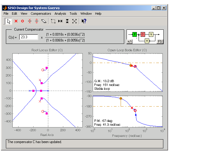
Your SISO Design Tool now looks like this.

Figure 4-35: SISO Design Tool with the Final Values for the Electrohydraulic Servomechanism Design Example
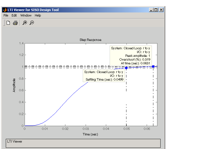
To see that this design meets the design requirements, take a look at the step response of the closed-loop system.

Figure 4-36: Closed-Loop Step Response for the Final Design of the Electrohydraulic Servomechanism Example
The step response looks good. As you can see, the settling time is less than 0.05 second, and the overshoot is less than 5%. You have met the design specifications.
 | Adding Poles and Zeros to the Compensator | Viewing Damping Ratios |  |