
| Getting Started |   |
Moving Compensator Poles and Zeros
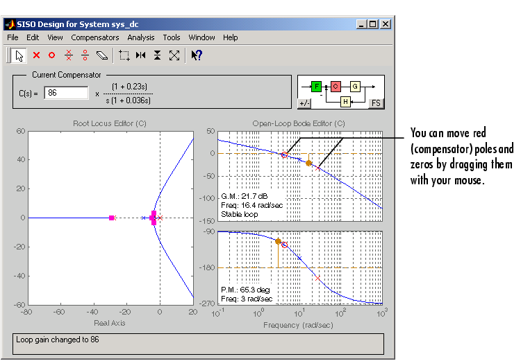
To improve the response speed, move the lead network zero closer to the leftmost (slowest) pole of the DC motor plant (denoted by a blue `x'). To do this, just grab the zero and drag it with your mouse. Try positioning the zero near the slowest plant pole.
Now try moving the lead network pole to the right. Notice how the gain margin increases as you do this. You can also adjust the gain to increase the gain margin; grab the Bode magnitude curve and drag it downward with your mouse to reduce the gain and increase the gain margin.
As you tune these parameters, take a look at the LTI Viewer. You will see the closed-loop step response alter with each parameter change you make. The figure below shows the final values for a design that meets the specifications.

Figure 4-15: Final Design Parameters for the DC Motor Compensator
The values for this final design are as follows:
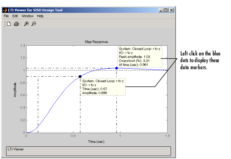
You can use the Edit Compensator dialog box to specify the exact values. Double-click in the Current Compensator panel to open the window. This figure shows that the gain margin is 22 dB, and the phase margin is 66°. To see if the design meets the rise time and overshoot requirements, go to the closed-loop step response, right-click in an empty region of the plot, and select Characteristics and then Rise Time and Peak Overshoot. This figure shows the plot with the rise time and overshoot denoted by large dots on the curve.

Figure 4-16: Step Response for the Final Compensator Design
The step response shows that the rise time is 0.45 second, and the peak amplitude is 1.03 rad/sec, or an overshoot of 3%. These results meet the design specifications.
 | Adding a Lead Network | Changing Units on a Plot |  |