| Simulink Reference |
  |
Bus Selector
Select signals from an incoming bus
Library
Signal Routing
Description

The Bus Selector block accepts input from a Bus Creator block or another Bus Selector block. This block has one input port. The number of output ports depends on the state of the Muxed output check box. If you select Muxed output, the signals are combined at the output port and there is only one output port; otherwise, there is one output port for each selected signal.
| Note
Simulink hides the name of a Bus Selector block when you copy it from the Simulink library to a model. |
Data Type Support
A Bus Selector block accepts and outputs real or complex values of any data type, including fixed-point data types, except int64 and uint64.
Parameters and Dialog Box

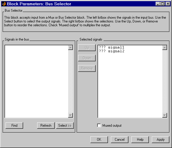
- Signals in the bus
- The Signals in the bus list shows the signals in the input bus. Use the Select>> button to select output signals. To find the source of any signal entering the block, select the signal in the Signals in the bus list and click the adjacent Find button. Simulink opens the subsystem containing the signal source, if necessary, and highlights the source's icon.
- Selected signals
- The Selected signals list box shows the output signals. You can order the signals by using the Up, Down, and Remove buttons. Port connectivity is maintained when the signal order is changed.
- If an output signal listed in the Selected signals list box is not an input to the Bus Selector block, the signal name is preceded by three question marks (
???).
- The signal label at the output port is automatically set by the block except when you select the Muxed output check box. If you try to change this label, you get an error message stating that you cannot change the signal label of a line connected to the output of a Bus Selector block.
 | Bus Creator | | Check Discrete Gradient |  |


