

| Getting Started | |
Viewing Damping Ratios
The SISO Design Tool provides design constraints that can make it easier to meet design specifications. If you want to place, for example, a pair of complex poles on your diagram at a particular damping ratio, select Design Constraints and then New from the right-click menu in the root locus. This opens the Design Constraints editor.
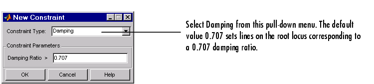
Figure 4-37: The New Constraint Editor
Applying damping ratios to the root locus plot results in a pair of shaded rays at the desired slope, as this figure shows.
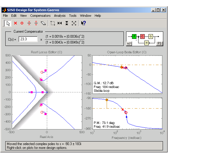
Figure 4-38: Root Locus Displaying 0.707 Damping Ratio Lines
Try moving the complex pair of poles you've added to the design so that they are on the 0.707 damping ratio line. You can experiment with different damping ratios to see the effect on the design.
If you want to change the damping ratio, select Design Constraint and then Edit from the right-click menu. This opens the Edit Constraints window.
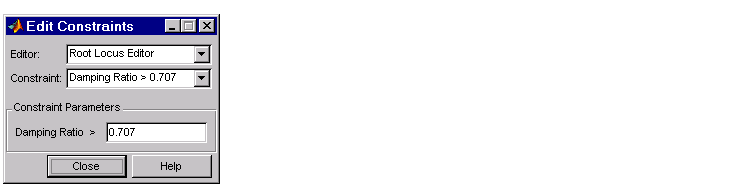
Figure 4-39: The Edit Constraints Window
Specify the new damping ratio in this window.
An alternate way to adjust a constraint is to left-click on the constraint itself to select it. Two black squares appear on the constraint when it is selected. You can then drag it with your mouse anywhere in the plot region.
If you want to add a different set of constraints, for example, a settling time constraint, reopen the New Constraint window and choose settling time from the pull-down menu. You can have multiple types of design constraints in one plot, or more than one instance of any type.
The types of constraints available depend on which view you use for your design. See Design Constraints in the Control System Toolbox online documentation for a description of all the constraint types available in the SISO Design Tool.
| | Editing Compensator Pole and Zero Locations | Exporting the Compensator and Models | |